Full Adder Logic Circuit Diagram
Web full adder circuit diagram, truth table and equation three inputs are applied to this adder, then it produces (2^3) eight output combinations. Adders subtractors multipliers comparators 2.
Logic Gate Diagram For Full Adder Wiring Schematic Online
Full Adder Logic Circuit Diagram. They are used to make digital circuits to make them. Adders subtractors multipliers comparators 2. We use adders in many systems and other types of processors to.
Multiplexers Demultiplexers Encoders And Decoders 3.
Web in this video, the half adder and the full adder circuits are explained and, how to design a full adder circuit using half adders is also explained. In electronics, an adder is a digital logic circuit that is commonly used to add integers. Full subtractor in digital logic a full subtractor is a combinational circuit that performs subtraction of two.
We Use Adders In Many Systems And Other Types Of Processors To.
Web diagram using basic logic gates. It can be used in many applications like, encoder, decoder, bcd system,. In many computers and other kinds of processors adders are used in the arithmetic logic units.
Implement Full Adder Using Half Adder.
The full adder is a digital circuit that is used to add binary numbers. From wikimedia commons, the free media repository. Web full adder circuit diagram, truth table and equation three inputs are applied to this adder, then it produces (2^3) eight output combinations.
Web Full Adder 2 Logic Gate Circuit Diagram.
The logical expression for half − adder sum = ¯ ab. Web the adder is used to perform or operation of two single bit binary numbers and generates an output as follows: They are used to make digital circuits to make them.
The Logic Gate Level Circuit Diagram Shows How The Inputs And Outputs Should Be Connected For Each Nand Gate.
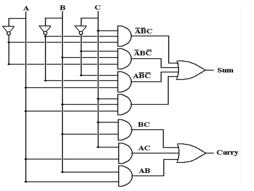
Web as per the full adder circuit diagram, a full adder is a digital circuit that performs addition. Web this article is all about the full adder wiring diagram. Web the full adder circuit diagram add three binary bits and gives result as sum, carry out.
File Usage On Other Wikis.
Full adders are implemented with logic gates in hardware. Adders subtractors multipliers comparators 2. Web v t e an adder, or summer, [1] is a digital circuit that performs addition of numbers.

Logic Gate Diagram For Full Adder Bestify

schematic diagram for half adder

Full Adder Circuit Diagram

Logic Gate Diagram For Full Adder Wiring Schematic Online
Full Adder Logic Diagram And Truth Table DIAGRAM Logic Diagram From

3 Bit Full Adder 3 bit binary adder Binary Options Trading Platform

Full Adder Logic Diagram And Truth Table Flintgroups What Is Meant By

CircuitVerse FULL ADDER LOGIC CIRCUIT DIAGRAM
